Glad you are finding it helpful!
My rule to date has been not to add more than an amp to the factory circuits. I have added lights and accessories all over this truck and tied many to existing circuits following that rule. I have not yet experienced any faults, failures, or problems and sure want to keep it that way! With them being monitored circuits I do not believe you could add very much, like double the load and not expect problems.
So I may have errored too much on the side of caution but 1 amp additional is my max and recommendation. Many of my adds are at or below an amp. All that are over I have gone the relay route.
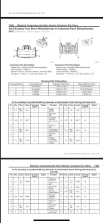
So for the running boards I would tap X1 Pin 1 and use that as the trigger wire to a relay with a constant battery feed power. I personally would run a power wire with fuse through the passanger side fire wall and cross that wire over to driver side under the dash. There mount the relay by the BCMs so it’s inside and protected and run your X1 Pin 1 to the trigger. Ground it the one of the ground points by the BCMs then run you outputs down the driver door sill and out of the cab through a hole in the driver door sill and down to the running boards and across to the other side.
Wish I knew the magic load number but haven’t found it. Hope some of this helps.
I did that approach tying and additional set of fog lights to the OEM circuit and no issues at all. Achieve the factory control without the loading.